It’s now time to start thinking about the control system behind Rhad Valley, and despite the unexpected cost of the frog juicer, I wanted to get back on track with this and keep things low cost. With this in mind I decided on DCC-Ex because it’s good (I’ve used it before) and it’s b****y cheap! It looks complicated at first glance, but when you see the price then it’s worth giving it a go:
- Arduino Mega – £15.76
- Motor Shield – £13.59
- Wifi Shield – £5.99
The only other things that you need to get this working as a DCC controller is a 5v power supply (a phone charger), a 15v supply (laptop charger) and a couple of male/female jumper wires – all of which you probably already have. So excluding the power, you’re looking at £35.34!
Obviously with it being low cost, the DCC-Ex system does have it’s limitations – mainly that you have to build it yourself, and you have to be comfortable editing a config file. That being said, the DCC-Ex team have created an installer which will walk you through step by step as Rob shows in this Youtube video: https://www.youtube.com/watch?v=H8wDb7iKrVQ&t=274s
I installed mine however by downloading the sourcecode from Github, and then used the Arduino IDE…
First, go to the official release page on Github (https://github.com/DCC-EX/CommandStation-EX/releases) and then download the latest release. Unpack the file somewhere on your computer and then navigate to the folder. Make a copy of config.example.h and rename it as config.h. Now open up the Arduino IDE, and from within there open CommandStation-EX.ino. This will now import all of the files needed into the IDE.
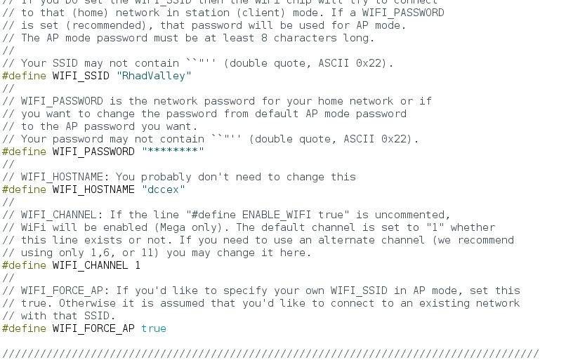
For my setup, I want to be able to connect directly to the command station with my phone so that I’m not taking a router to exhibitions with me! So with the IDE open, switch to the config.h tab. Scroll down to #define WIFI_SSID and give it a network name; in my case “RhadValley”. Next change the WIFI_PASSWORD – if you don’t then anyone running Engine Driver on their phone could connect to your layout and start controlling locos! Finally, change #define WIFI_FORCE_AP to true. What we have done here is set the arduino to give out a wifi network that you can search for and connect to with your phone. Save the file (Ctrl+S) and then with the arduino connected to your PC, upload the sketch.
Now it’s time to put the parts together…
On the back of the motor shield there are two pads labled Vin – you must, MUST MUST seperate the two with a blade. If you fail to do this, when you connect your 15v supply to the shield it’ll simply fry the arduino. So do it! Now place the motor shield onto the arduino and connect your 15 power in into the Vin (pos) and Gnd (neg) terminals. Next, connect the bus wires to the A terminals.
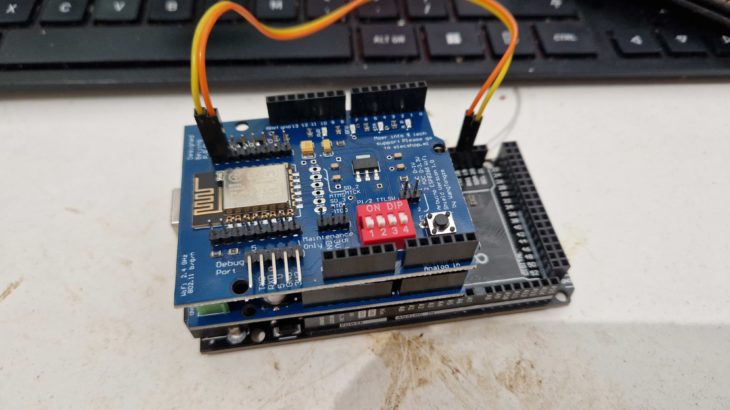
Next take your wifi shield and (if you’re using the same one as I am) bend pins 0 and 1 out of the way as we don’t want these going into the motor shield. With that done, put the wifi board on top of the motor shield. Finally, connect the top pin next to the chip to terminal 19 on the arduino, and the pin below that to terminal 18.
All done!
To test, connect the arduino up to a phone charger using the USB cable and turn on the 15v supply. Wait a few seconds and then search for the wifi network, connect to it and ignore the warnings about no internet. Now open up Engine Driver and you should be able to connect to the command station – if it doesn’t show already then you can use 192.168.4.1 on port 2560. Once connected, click on the 3 dots in the top right and click on “power”. Using the power button, toggle between on and off, and you should see a light go on and off on the motorshield. If you do then you’re ready to run locos!
In the next update I’ll show how I took my setup one step further and programmed in a roster of my locos and defined the points and even set routes.
See you then