In the last post, we finished off by wiring up a bus wire for all of the common terminals of the solenoid point motors to connect to, and this is where we pick it up. The layout currently has old fashioned solenoid point motors – think classic Gaugemaster PM10’s and then think older! These motors only have three terminals; positive, negative and common return. If I were building the layout from scratch then I would have gone with Seep motors as they can switch the polarity of the frog, but we want to keep the layout cheap so we’ll work with what we have.
The DCC control system that I have decided to go with on Rhad Valley is DCC-Ex – an Arduino based system which will keep the whole thing rediculously low cost. You can build a command system to connect to your pc for around £20, or wireless via Wifi to your phone for around £30. When you think that a NCE Powercab is around £200 more than that, you can see why I’ve decided to go down this route. I’m also a programmer by trade, so the flexibility that the DCC-Ex gives you with regards to automation and sensors etc, it’s a no brainer to me.
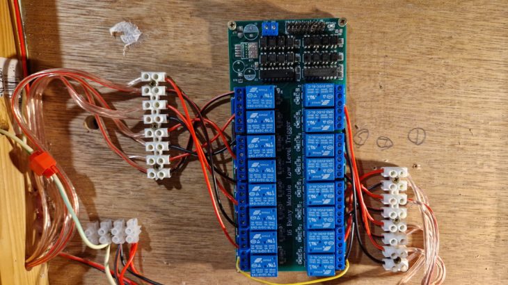
Normally the method of point control with DCC-Ex is with servos rather than solenoids, but again we want to keep this build low cost so we have to work with what we already have. The problem we have here is that an Arduino can’t control solenoids by itself as the solenoids require an analogue switch with a CDU. So to this end, we’ll have to use a relay board to act in place of an SPDT switch; we’ll use one relay to power the motor one way, and another to power it the other. All of the middle terminals of the relay will be connected together and then onto the CDU, with the Normally Open (NO) terminal of the relay will control the direction of the motor.
With that all wired in place, we’ll leave it there for now as we haven’t set up the Arduino yet. Next on the agenda is powering the frogs with a juicer…
16 channel relay: https://amzn.to/4dT0n8Z
Yes, this does work. I used Shaun’s example and based on the questions I asked him, these descriptions may be of use to others to clarify the physical wiring.
You need a 5vDC power feed to the relay card – I used a mobile phone charger with the plug cut off and the wires bared (or you can use a jack plug to fly-lead adaptor but that’s just extra cost)
Important – you need to ensure the relay card doesn’t have the 5v JD-VCC jumper in place. If it is, remove it or you’ll backfeed the Arduino and it will be very unhappy with you.
You DO need the GRD jumper wire from the relay card to the Arduino to complete the return for the relay trigger.
I can only speak for dual solenoid at the moment so;
The CDU common feed goes out to all the point motors. I did this using Gaugemaster triple point wire and used the red as the common feed. I daisy-chained an 8-terminal chocolate block ‘bus’ to the CDU feed and then connected each point wire red cable to a terminal on that bus.
The CDU switched feed go to the first relay and then you daisy-chain all the other relays to that. Use the centre screw terminal on all relays for that daisy-chain.
The switch wires from the relay to the point motor are done in pairs and use the terminal with the right angle symbol on it, not the symbol with a dog-leg.
If you code up relay 1 for Throw(T) and Relay 2 for Close (C) then you need to wire the appropriate end of your point motor back to either relay 1 or 2. That gives you your first turnout. Rinse and Repeat for (up to) the other 7.
I used the green and the black on the point wires for the switched feed. (Green for Throw and Black for Close)
If you get the wiring the wrong way around you can either simply swap the throw and close wires over between the relay pair or if you’ve had enough crawling under the baseboards by then, modify the arduino code and reprogram the controller.
My CDU is a Gaugemaster variant that takes anything between 12 and 24vAC according to the instructions. Mine runs just fine using a 19vDC HP laptop power brick. They relay power burst is set by the Arduino for a 50ms activation. My setup works well for me with with Seep PM1 motors.
As the relay card is Opto-Isolated (it uses an LED las a light source on the 5vDC side to trigger the optical sensor of the relay on the CDU side) there is no physical risk of sending CDU power up to the arduino PROVIDING you have disabled or not fitted the JD-VCC jumper. The GRD jumper to the arduino is on the 5vDC side so matches the 5vDC of the arduino itself.
Hope that helps.
Any question – please post here (or come along to a Friday evening session)